Tuesday, July 23, 2013

6. Last week!

Time flies! We're only left with 3 weeks in US, and this Friday we'll have the rolling frame inspection :3..... So we submitted our waterjet file today and adjusted the seating and put everything together:
kart with no name 
As you can see from the photo, the right wheel is actually not on the kart. It was good at first, but after I sat on it for like 10 seconds, the wood inside the steering part broke... We think the 1/4'' aluminum plates would be fine ;p

This week we also need to finish the electrical system of the kart. Looks complicated. Starting tomorrow!!!

NIGHT!

Friday, July 19, 2013

5. Final prototype

front frames not stable 
 Last week before the rolling frame inspection! We finally put the kart together !!!! We still met some challenges and we managed to solve them all - - .

We were arguing about where we should put our knees on the kart. Should it be on the intersection between the front horizontal frame and the vertical frame? Or back off a little bit and avoid that intersection? It turns out that it doesn't really matter. So we are avoiding that part cause that way is more comfortable for the driver. We tried to sit on the kart the other night, and the front frame just kind of sinked a bit... It turns out that we didn't fasten the joints enough. And it's probably because of the wood, and there is no aluminum plate at the top to squeeze the whole structure together.
         
Our solution was to secure a long horizontal aluminum frame at this critical joint. We cut the battery deck cause it doesn't really need that much space. So we used that part to do the new four joints.

We put on everything, newly adjusted front wheel s, back wheel, motor, batteries and controllers.

Looks pretty good, now all we need is the steering wheel and the seating !!!!


Friday prototype
Friday! We did the steering wheel and the test turns out to be pretty good. It's easy to turn but not that easy. And we also found the bolts and nuts to secure the controller to the battery deck, a way to secure the brake. I think we got the sensor mount too....A little problem was that the steering rod appeared to be a little bit shaky, it turns out that we missed one shaft collar, so we are moving three holes a little bit forward to avoid the shaft collar from hitting the aluminum frame. 

All we are left is the seating, which is quite tricky to secure. We bent some L brackets and the holes are very tricky to drill. which took us quite a long time. SHOULD TRY FINGER JOINTS NEXT TIME!!!

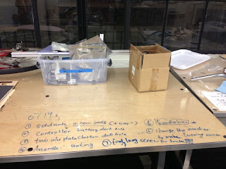
our clean and organized table - -
I've finished all the drilling and assembled half of the kart. Shall do the other half tomorrow and make some slight changes to solidworks files, then our mechanical system is done and we can start doing our electrical system ;p Oh right, haven't put the wooden support for head yet. We'll just use a shaft collar I guess.... 

Night!

Tuesday, July 16, 2013

4. Building and more cading

So we tested out our first prototype, and it didn't look good :( The triangular seating was not very comfortable and the joints were kind of splitting in the middle (probably because of the wood we used). But still not very safe. We wanted to do something different, so we started cading again and figuring out a way to make the kart look nice while still maintaing the kneeling down gesture. Jiawei has figured out ways to do the front wheel and also support for the motor. Our ideas evolved from initially a dove shape to a snoopy shape, and now we're settled on the phoenix shape.

We're bending the 1/8'' aluminum plate to make the entire shape, but we're still not sure whether we should split the whole shape into two parts and waterjet them on two separate aluminum plate or just waterjet the whole part on one plate. Still need to figure that out on solidworks.

.........(ONE WEEK PASTS)

We bent the 1/8'' aluminum plate to make the 'seat':

aluminum seat 
It turns out a bit different from what we thought before cause we never considered about the limitation of the metal bending machine..... LESSON LEARNED! There should have been two more bends to make the knee deck so we can just secure the knee deck to the aluminum frames sticking out from the side. So we changed the plan and decided to use the rest irregular pieces of the 1/8'' aluminum plate to make some bent L-shape brackets to secure this seat to the separate knee decks which are then secured to the aluminum frames.... So one of the top things on the list: cut the rectangles and bend the brackets!

And motor support after several changes:


And rear wheel :
Oh yes, and for the cushion, I was learning stuff at the solar ev team downstairs, and we were waterjetting pink foams last Friday night so there were some leftover foams and I borrowed one piece:

Now the only thing left is steering and it's something we're struggling the most. The first few prototypes all broke when we tried to turn and the recent one we did earlier today doesn't turn properly. We added in some washers in between the two round joints to fit in four wooden sticks so that the hole drilled in the middle doesn't make the structure too fragile. For the turning problem, turns out that we need to increase the torque by increasing the distance. So we did this prototype later this afternoon:
And it looks ok, but we still need to do a final test later tonight - -
Brake lever and thumb throttle on our aluminum tube ;p:
Another thing on the list is to bend the aluminum tube for the steering, that's the one in the above picture....

Our budget review till now: 
Item Number  Model Budget:500
motor  1 turnigy aerodrive 6374-149 76.53
controller  1 KBS48121 149
battery  1 A123 75
rear wheel assembly 1 200x50 Rear Wheel Assembly for Chain Drive Razor E200 (Versions 5-27) 25.99
front wheel 1 200x50 (8"x2") Front Wheel Assembly for Razor E150 23.99
Pedal/Sensor 1 Thumb Throttle with 48 Volt Power Meter 17.99
Ball Joint Linkage Shielded, Steel, 1/4"-28 4 6058K25 11.76
Alloy Steel Threaded Rod Plain, 1/4"-28 1 92580A107 (3ft) 4.78
Aluminum 3/4" steering shaft 1 9056K693 (no use) 7.39
screw 1 92196A636 5.22
Brake lever 1 15.99
Switch 1 F48-5595 8.99
1/2 aluminum tube (vertical) 1 1658T45 share Andrew (4 ft) 3.5
7/8 aluminum tube (horizontal) 1 9056K723 (1 ft) 7.39
shaft collar 6 6436K14 19.8
nuts 1 91845A031 (free!) 0
brake cable  1 downstairs?  453.32
So we still have 46.68 dollars left... We still need to get the brake cable and the switch.... And we haven't done the electrical part yet, though it looks like we have everything we need in the lab but still we are saving the money in case something breaks....

Two more weeks before the rolling frame inspection!!!! We were late for the waterjet submission for this week cause our steering problem suddenly propped out so we needed to fix that :p But we've finished the technical drawings and managed to fit the parts on one single sheet (1/4'') Shall wait till next Tuesday!! And hopefully we can put everything together and do a test run this week.


Wednesday, July 3, 2013

3. CADing and prototyping

dimension drawings....
solidworks model

This week,we received all the parts we ordered last week and have been busy CADing on solidworks. We kind of come up with the mechanical structure of the whole kart, how to build it with the materials we have (80/20 aluminum frame, 0.125'' and 0.25'' aluminum plate). After figuring everything out, this is what we come up with:

So we are still adopting the 'kneel down' gesture. And we decided to let the driver (which would probably be me) put her chin on the chin support structure (the tallest thing in the picture) And the person is sitting on the triangular-shpaed structure. We first thought that the two vertical aluminum frame would be a good support for the driver as he makes turns, so there will be some force given to the driver to avoid them from being thrown out of the kart. BUT, our first prototype proved that it would not work....

We laser cut the joints with plywood, and cut the aluminum frames. We made our first prototype of the chassis last night:
bike from the recycle bin, could be useful in the future?
parts we've ordered ;)


Jia wei working on the annoying screws
Everything looks so tiny when we actually make it....Anyway, lessons learned: don't design a structure that needs too many joints to connect. The screws are very annoying and the thing with those 80/20 aluminum frame is, if you mess up one screw, you may have to unscrew the rest and do it all over again....And the frames all have sharp edges so be careful! One problem we are running into right now is at some parts, the joints are not strong enough to hold the whole structure. We're guessing it's probably because of the property of the plywood and we didn't use the proper setting when we laser cut so some parts are burned a little bit and the whole wood is kind of crispy. Maybe it will get better with aluminum plate, if not then I guess we'll just have to buy steel plate....ALSO, always remember to delete those crosses on your dxf file before sending them to lasercut.....Or you may ruin the whole joint. I'll post a picture of our first physical prototype later tonight or tomorrow. We're also exploring different methods of joining parts together....And Jiawei drilled the holes on the gear to fit our motor and adjusted the holes on the washers, so we'll probably assembly the rear wheel today or tomorrow. Front wheel we'll just need to wait for our second BOM to arrive :p